My First Walking Beam Stirling engine build with pictures
Posted: Thu Sep 03, 2015 11:33 pm
From start to finish.. (build currently still in progress)
Casting the Flywheel
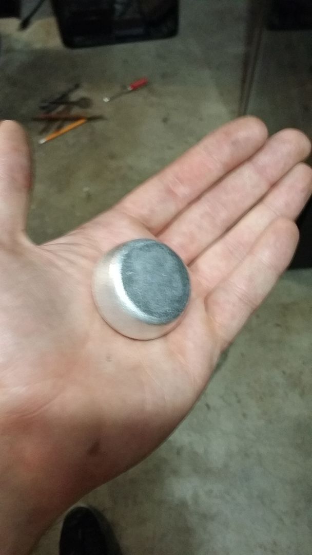
Aluminum ingots made from soda cans
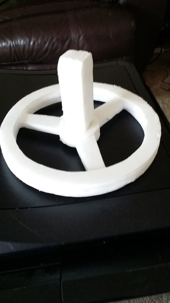
Flywheel made from foam
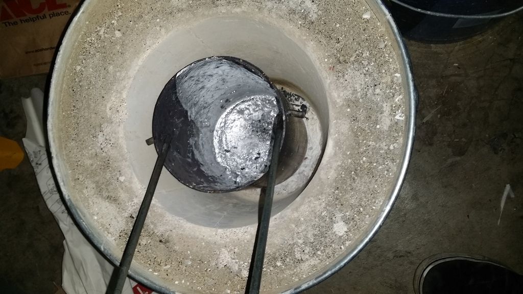
inside forge after the pour
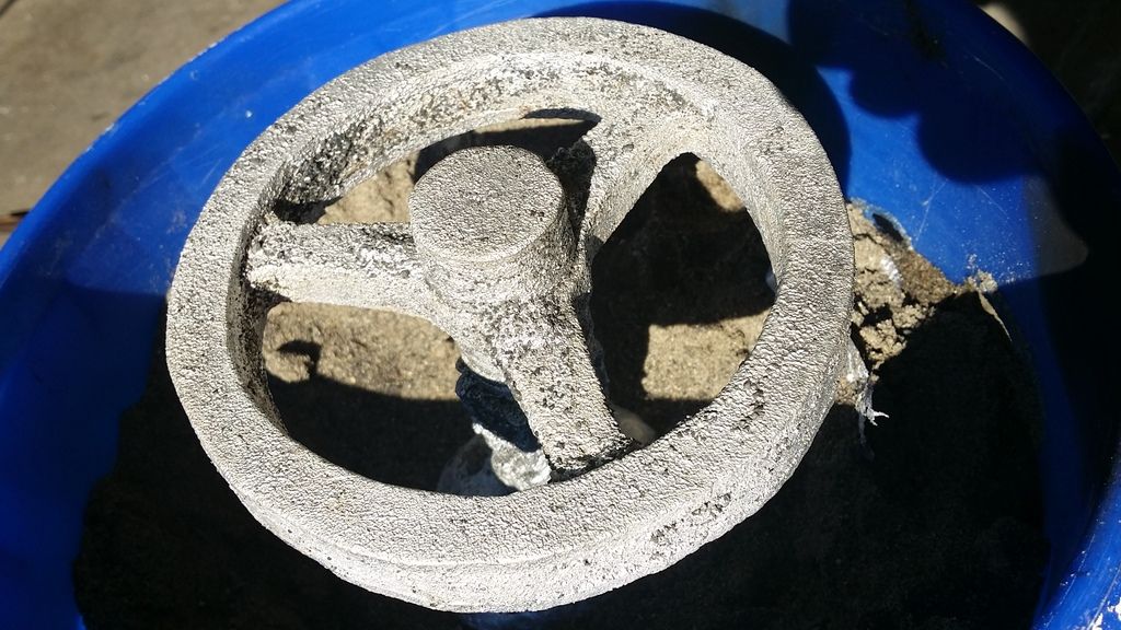
first was a failure, got a bit intimidated with a foot and a half of flames shooting out towards my face while pouring molten aluminum so I hesitated, causing this mistake. Live and learn...
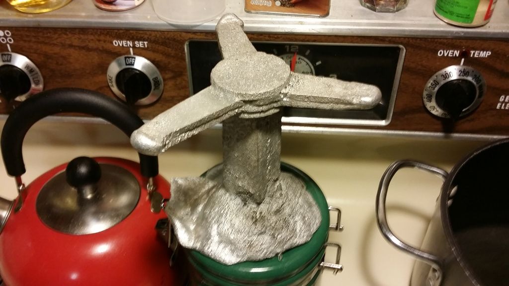
Second casting was a success!
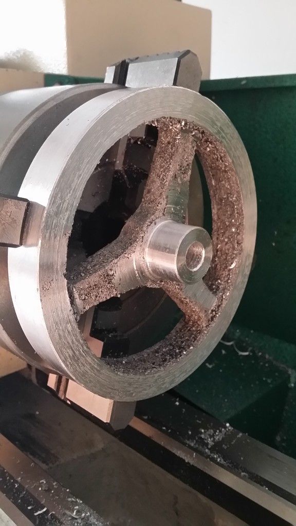
Turning the flywheel on my 12x22 inch grizzly metal lathe, the overall outside diameter is six inches
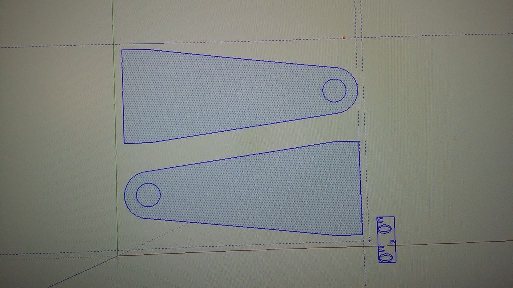
Flywheel supports
I decided it would be fun to use my homemade CNC router to make these. I designed them with Google sketchUp
With bearings
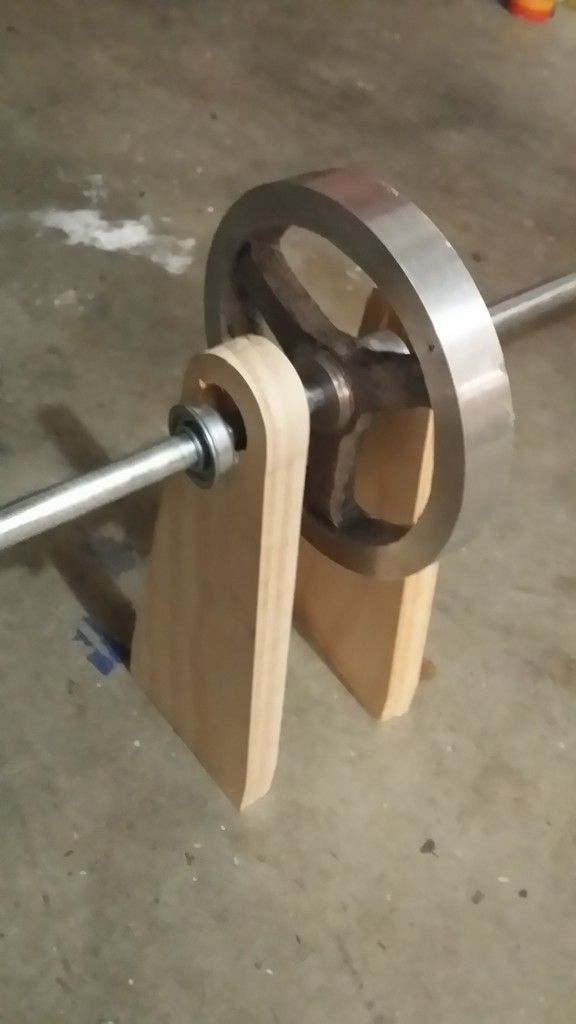
More support
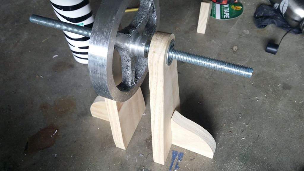
Staging Middle Support for Rocker arms
These parts were also cut using my homemade CNC, These will not be the cylinders I will be using, they are being used for placement and planning
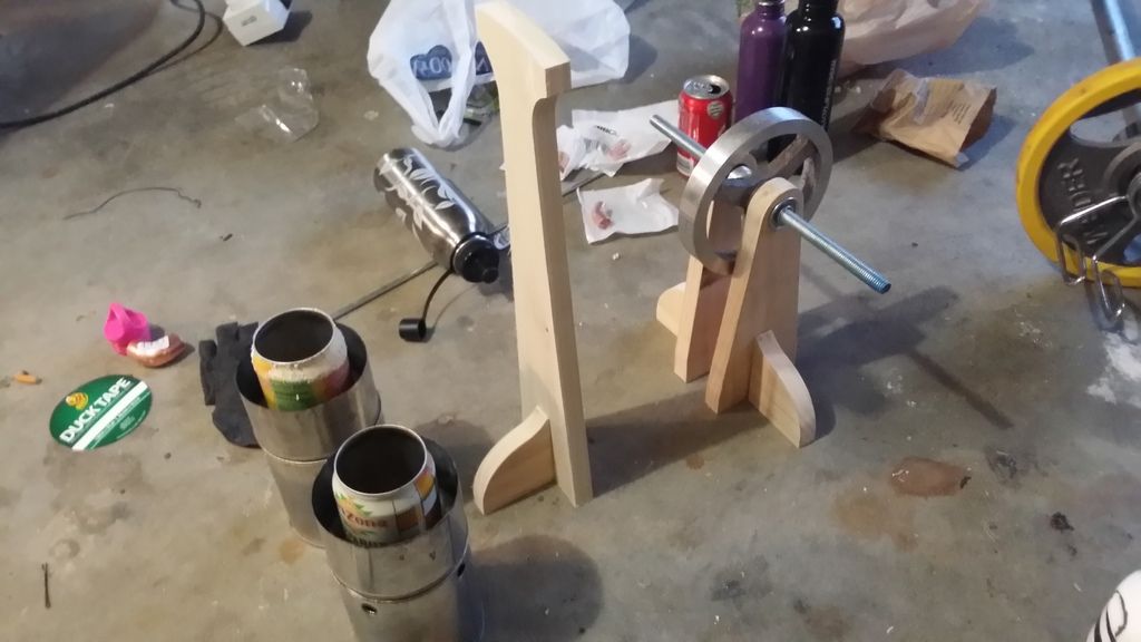
another
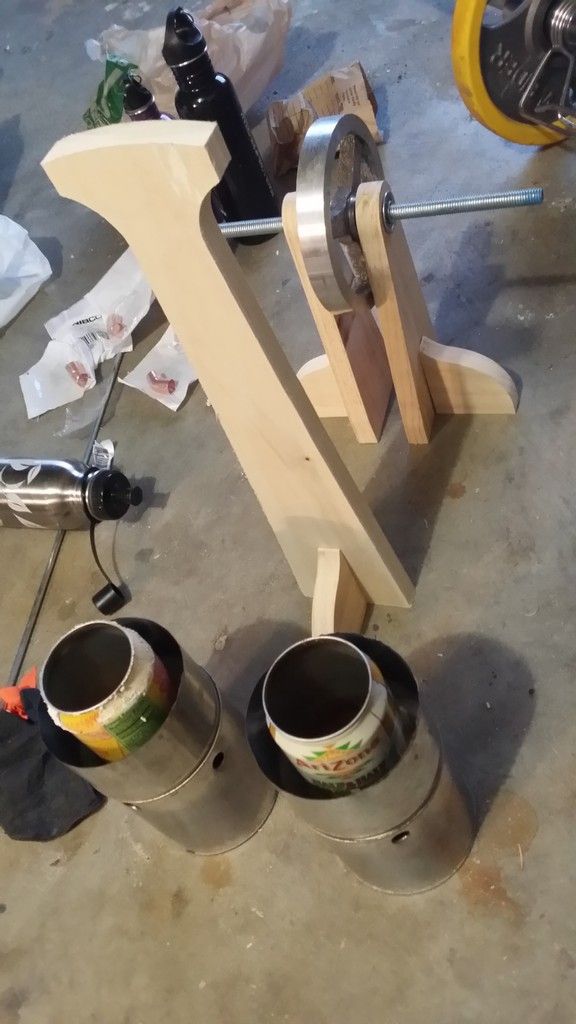
Building the Main Cylinders
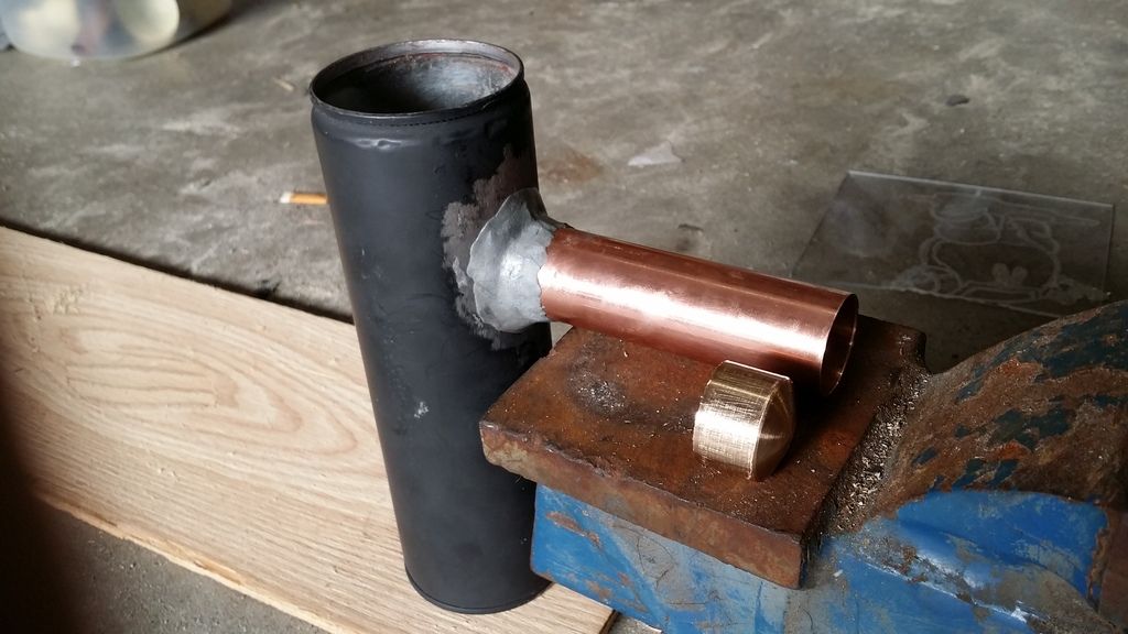
Hightemp JBweld used to joint 1 inch copper pipe to Large spray paint can
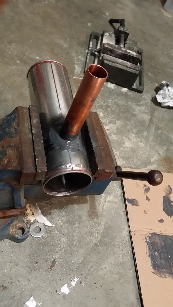
with brass piston
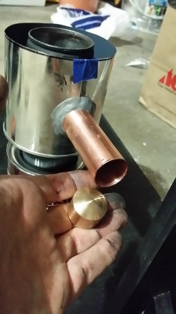
Water jacket and bottom heat shield installed. Hightemp fireplace adhesive rated at 2000 deg F was used as well as high temp JB weld on the cold side
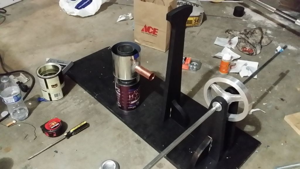
Started painting a bit
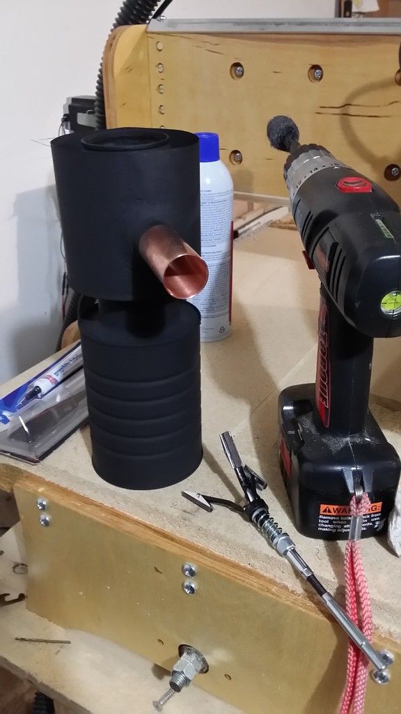
More paint! High temp rated at 1200 deg F. Honed out the cylinder wall with a brake hone, as well as steel wool wrapped around a drill bit to polish it up for 10 minutes
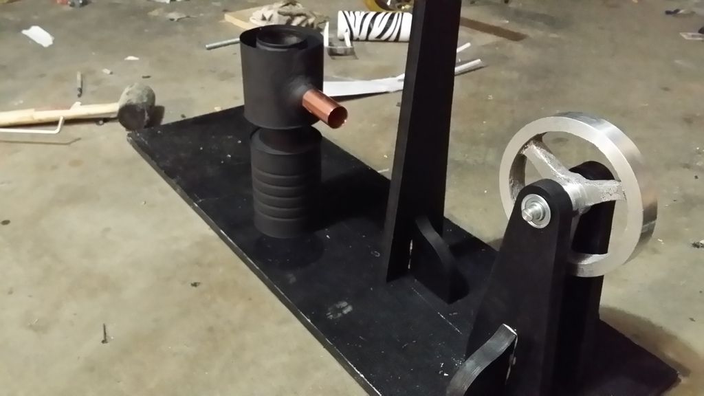
New Chimney!
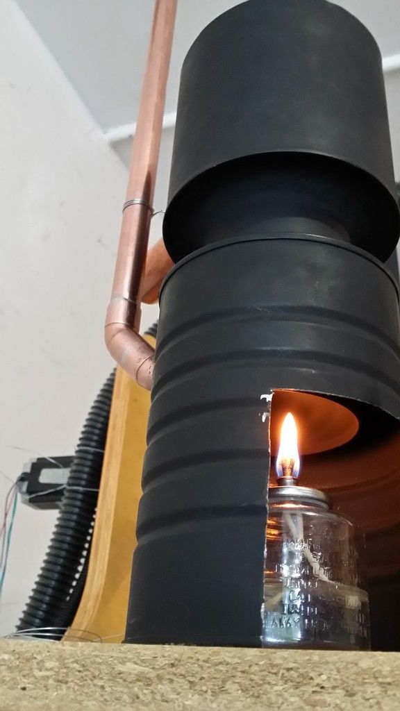
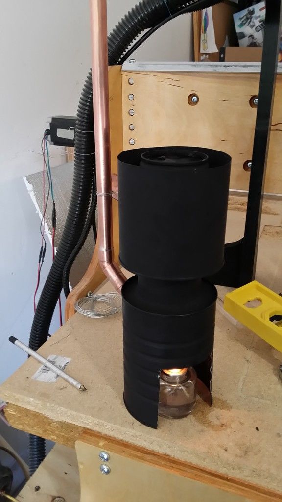
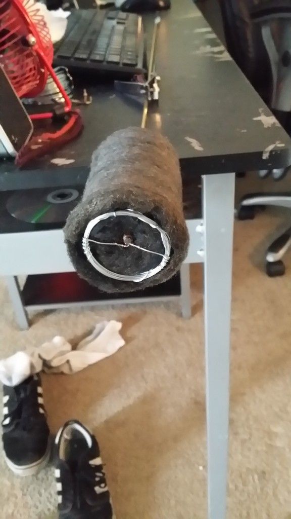
Displacer Piston
2.5 inch diameter, 2.5 inch stroke in the large spray paint can
Power Piston
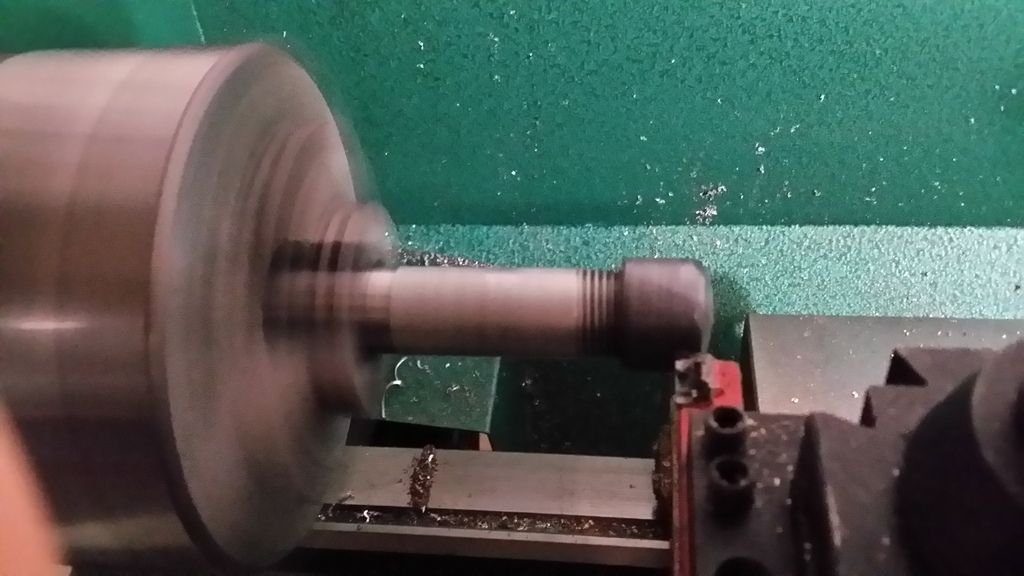
Brass 3/4 endcap was spun down and coated with a 2 part epoxy/graphite mixture and let to set overnight, spinning it on the lathe
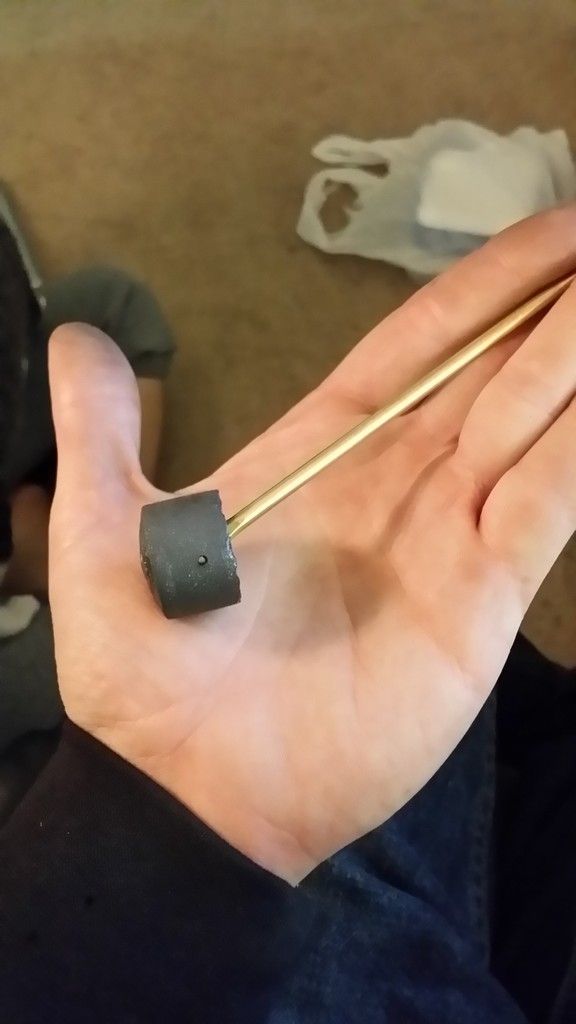
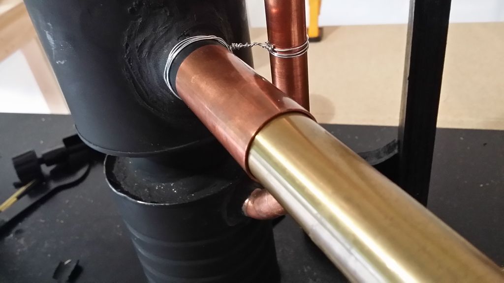
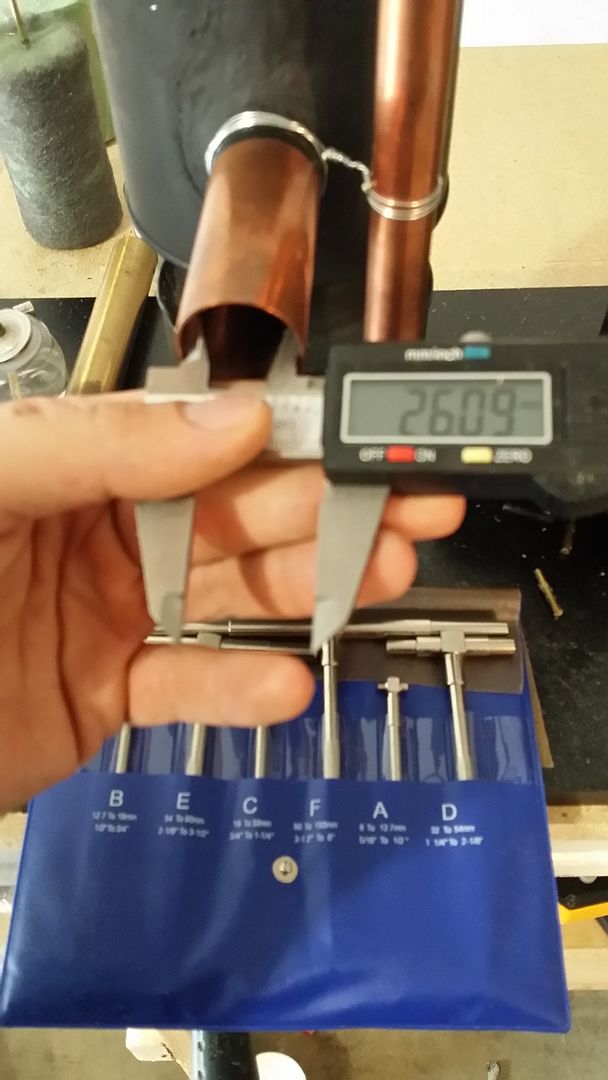
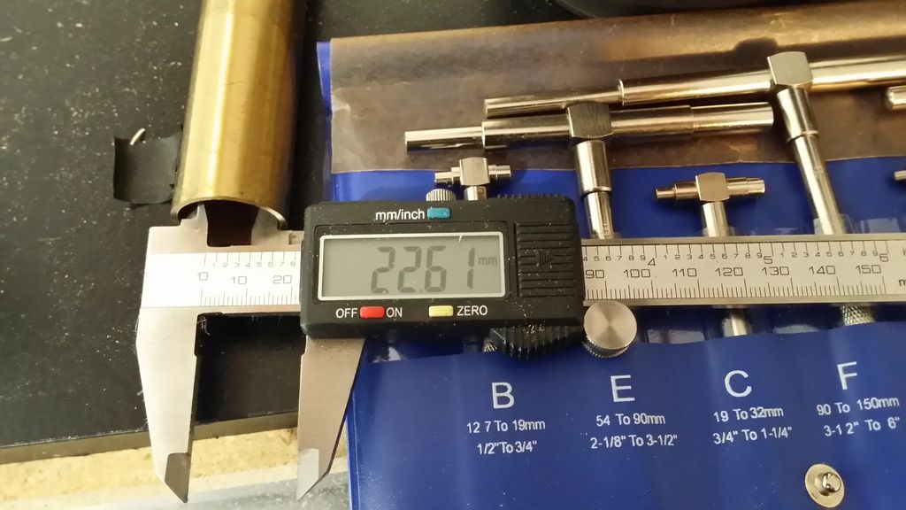
Linkage connected to power piston. It takes over 20 seconds for this piston to travel 3 inches when making it airtight and letting gravity pull the cylinder downward inside of the copper tubing. It's almost impossible to make a copper pipe from the hardware store completely round without a boring bar(which I don't currently have) that I'm aware of, it's not perfect but it will do for now. Thinking replaceable piston wall inserts for the near future.
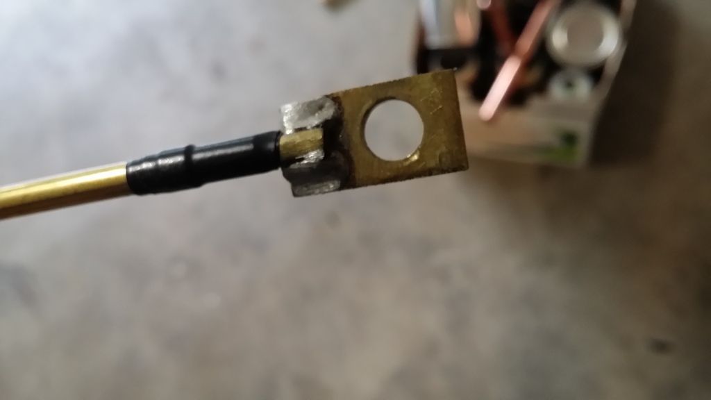
High temp silver solder
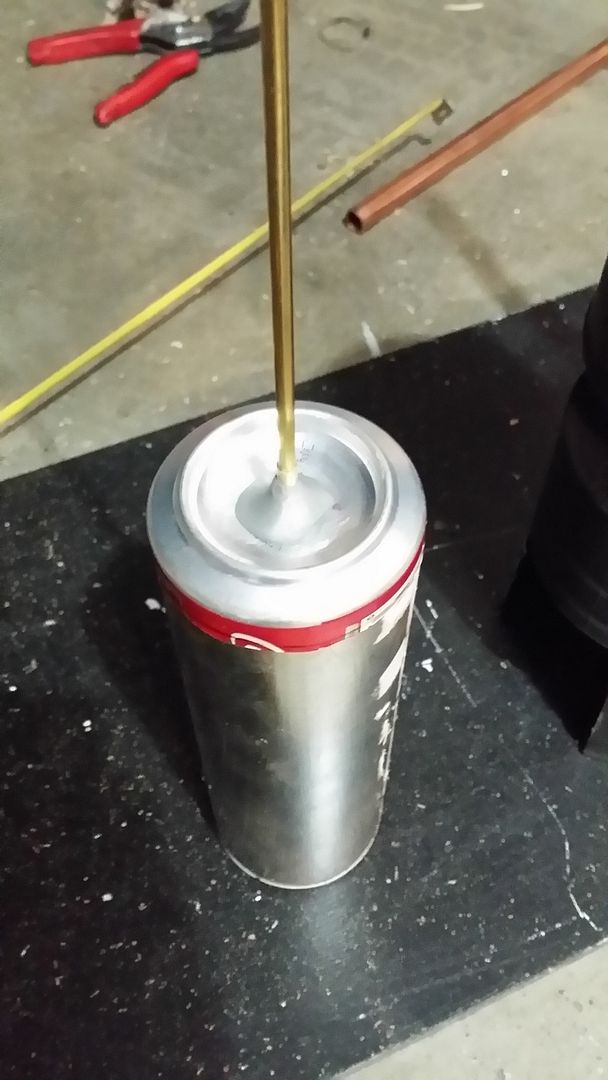
Pressure chamber top, aluminum can was used as it fits perfectly over the top of my paint cans used. High temp JBweld was used to fix the brass tubing to the aluminum.
I did the first bore stroke test tonight, I heated one side of the engine and move the displacer piston giving my power piston 3 inches of travel. Now I know the cam should be offset by 1.5 inches.
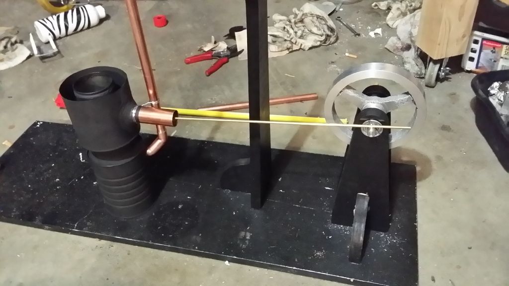
Cam
1.5inch offset from center.
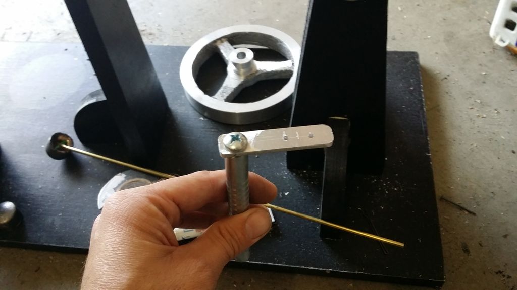
Brass bushing was used to reduce friction
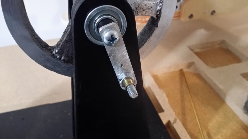
another
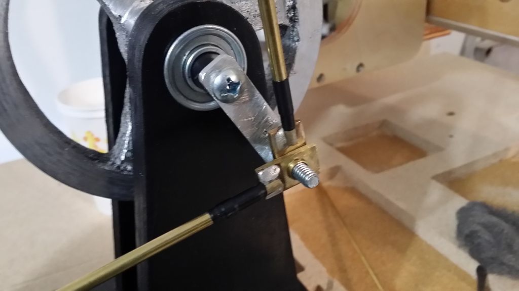
Possible piston sleeves
9/7/2015 half way there!
https://www.youtube.com/watch?v=eYSXhhPnEPE
9/13/2015 Engine tweaks!
https://www.youtube.com/watch?v=6mKWvn00njU
9/17/2015 More photo's added above!
More to come, I'll post as I build!
Casting the Flywheel
Aluminum ingots made from soda cans

Flywheel made from foam

inside forge after the pour

first was a failure, got a bit intimidated with a foot and a half of flames shooting out towards my face while pouring molten aluminum so I hesitated, causing this mistake. Live and learn...

Second casting was a success!

Turning the flywheel on my 12x22 inch grizzly metal lathe, the overall outside diameter is six inches

Flywheel supports
I decided it would be fun to use my homemade CNC router to make these. I designed them with Google sketchUp

With bearings

More support

Staging Middle Support for Rocker arms
These parts were also cut using my homemade CNC, These will not be the cylinders I will be using, they are being used for placement and planning

another

Building the Main Cylinders
Hightemp JBweld used to joint 1 inch copper pipe to Large spray paint can

with brass piston

Water jacket and bottom heat shield installed. Hightemp fireplace adhesive rated at 2000 deg F was used as well as high temp JB weld on the cold side

Started painting a bit

More paint! High temp rated at 1200 deg F. Honed out the cylinder wall with a brake hone, as well as steel wool wrapped around a drill bit to polish it up for 10 minutes


New Chimney!


Displacer Piston
2.5 inch diameter, 2.5 inch stroke in the large spray paint can

Power Piston
Brass 3/4 endcap was spun down and coated with a 2 part epoxy/graphite mixture and let to set overnight, spinning it on the lathe

Linkage connected to power piston. It takes over 20 seconds for this piston to travel 3 inches when making it airtight and letting gravity pull the cylinder downward inside of the copper tubing. It's almost impossible to make a copper pipe from the hardware store completely round without a boring bar(which I don't currently have) that I'm aware of, it's not perfect but it will do for now. Thinking replaceable piston wall inserts for the near future.

High temp silver solder

Pressure chamber top, aluminum can was used as it fits perfectly over the top of my paint cans used. High temp JBweld was used to fix the brass tubing to the aluminum.

I did the first bore stroke test tonight, I heated one side of the engine and move the displacer piston giving my power piston 3 inches of travel. Now I know the cam should be offset by 1.5 inches.

Cam
1.5inch offset from center.

Brass bushing was used to reduce friction

another

Possible piston sleeves


9/7/2015 half way there!
https://www.youtube.com/watch?v=eYSXhhPnEPE
9/13/2015 Engine tweaks!
https://www.youtube.com/watch?v=6mKWvn00njU
9/17/2015 More photo's added above!
More to come, I'll post as I build!