Crikey zhivko, you have really been doing some work on this baby,
I studied autocad a few years ago but haven’t had a reason or a copy or a decent computer to run it on for a while (although I wish I had a working copy of late). I can appreciate the effort you have made, also I used to work in the metal fabrication industry and i like what you have done so far (sweet!).
I have been reading your topic with interest and have had a few thoughts about some possible retrofit ideas. That being said I don’t want to distract you too much from the good ideas and possible alterations to geometry that the other guys have suggested. Its very solid information from some very experienced fellows, so take my ideas with a grain (or bag) of salt, also if my thoughts are bad ideas, I hope they will say so, so that I don’t lead you too astray.
Firstly as another option for placing steel (or other type wool) around the displacer, here's a possible alternative
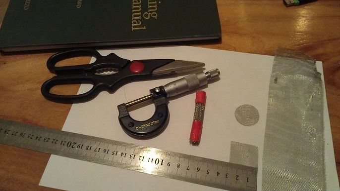
vamoose wrote:Here is a possible material for regenerator use. Its called 'termimesh' in Australia (and is a termite barrier material used in the construction industry). It is a stainless steel interwoven mesh that is around 300 microns in thickness, with strands 150 microns in diameter and has about 22 strands per 10 mm. It can be cut with heavier duty scissors, its not too rigid and can be manipulated into shape as its quite malleable. I guess it might be available from pest controllers in other countries with termites. I've been informed its not covered in any chemicals but is just a physical penetration barrier.
(I just picked it up off a job site rubbish pile)
vamoose

vamoose wrote:
had a closer look and it's 15 threads every 10mm, don’t know how I got it so wrong, I must be in need of a monocle ...or 2.
vamoose
(from what i've found) The width of the mesh is 300mm and comes in a basically a continuous length, And as opposed to steel wool you shouldn’t get the particles from the wool that can become free floating ebrasives, also I think it may be able to be wound so that it conforms to the displacer radius fairly closely . I'm not suggesting this is a great alternative but its an option.
Also another alternative (disregarding the first suggestion)- possibly, if there is enough room you could introduce a thin sleeve with a small clearance between it and the displacer (with the larger gap between the sleeve and the cylinder wall), and then wind mesh “bandage wound” around the sleeve outwardly to firmly fill the gap between the sleeve and the cylinder wall (and then 'insert' into the cavity). This could then possibly act as a hot end heat exchanger, regenerator, and then cold end heat exchanger (you could also divide the mesh into 3 different sections (rolls) so they are more physically isolated from each other).This insert would obviously have to end at the point of the top stroke of the power piston.
A loose (or firmish) seal could then be located between the small gap of the displacer and sleeve to encourage the working gas to flow through the new outer 'manifold' and the hot and cold ends (and regenerator).
Just some thoughts
vamoose
