My goal is to build a power producing engine, even if it is only a couple watts. I have an idea in mind to eliminate some of the nagging issues, like properly sealing pistons, Keeping the maximum practicle distance between the hot, and cold sides, reduce heat migration through the engine/framework itself, and also to keep the flywheel, and generator as far removed from the heat as possible. My heat sources will be the heat from my chimney, directly on my wood stove, or possibly solar in the summer.
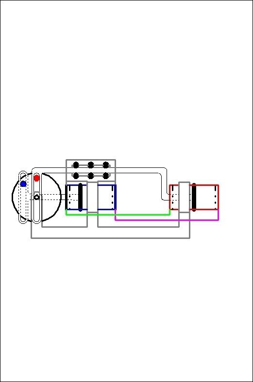
Esentialy what I would like to is have two cylinders in line with one another, with one being hot, and obviously the other cool. What I want to do is enclose both cylinders with only a sealed shaft leaving each cylinder. Then to conect the cylinders in two locations for each cylinder so the there are two power stroke per revoltion with the pistons exerting force in one direction, or the other depending on the location of the piston inside the sealed cylinder. I am not sure how to describe it exactly so I have a two simple diagrams that will hopefully make more sense.
This one is a rough view of what my vision is.....

I made a mistake in the drawings by only giving a 45, and not a 90 degree phase on the crank. Hopefully this is something this can be overlooked in order to get the idea because I am not cad master, and this took me too long to redraw until I feel more comfortable with the design. At any rate, I hope you can see the following couple modifications to reach my goals. The first being the orientation to separate the hot from the cold by placing them inline, and using two different connecting points on the crank to keep one piston 90 degrees from the other. Sealing the cylinder with only one shaft for each so that is the only potential area for air to escape, and keeping the pressure on either side of the piston a little more equalized to minimize blow by on the piston. The sealed cylinder should also keep the piston, and cylinder walls relatively warmer by eliminating the ambient temp air from contacting the back of the hot side piston, and also the exposed cylinder walls as the piston would traditionaly be at the TDC location. And of course the most obvious which is extracting twice the energy for roughly half the space, and weight.
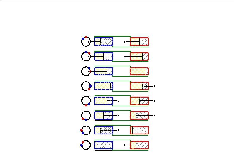
Here is another picture with a phase by phase progression from top to bottom. Again the piston are drawn 45 degrees apart, but should be 90. Another missleading thing about the picture is that the cylinders are shown as the same volume, but I realize the hot side should be about 150% of the cool side. Also, the black lines are supposed to be arrows, but are hard to make out in this view.

I think this may work, and my two basic questions are... What diameter should the connecting tube be in relation to the piston bore? Also, when the piston is at the end of its stroke shold there still be a small volume of air, or is it best to evacuate as much as possible?
Thanks in advance for any advice, and I hope to hear from some of you who can help.