I am wondering if this is a new idea that allows one to tie the beta stirling displacer directly to the piston head, or if this concept has been done before:
http://davesplanet.net/davesplanet/doub ... ng-engine/
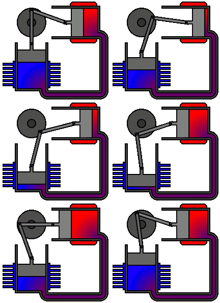
If you are willing to have two hot spots or two cold spots then it seems as if the movement of the displacer might be simplified to the following animation:
Dave
Double Cooled beta stirling engine
Re: Double Cooled beta stirling engine
I don't think that would work. Since the displacer needs to leave space for the gas to flow around it, the gas will be constantly heated. I think it would find a steady state and stay there..
Re: Double Cooled beta stirling engine
Sorry Dave, no way, you'll have to go back to basics and understand how a Stirling Engine works. Ian S C
Re: Double Cooled beta stirling engine
Dave i also don't think it would work on first appearances ....
BUT,
after looking at your animation for some time
I do kind of get why you ask...
There are a whole lot of working, lamina flow and acoustic engine designs that confuse and perplex me.
I guess the best way to figure these things out is to build it and see.
Better you than me.
vamoose
also i would suggest that with this kind of design, it would not be considered a Beta style, as it's a single motion configuration..
-
- Posts: 22
- Joined: Thu Mar 14, 2013 9:38 pm
Re: Double Cooled beta stirling engine
That's why I came to you guys, cause you know way more about stirlings than I ever will.
I left the flywheel off the diagram for simplicity, perhaps that is leading to some confusion?
This design seems trivially similar to the beta.
Cool air is forced to the hot region when the piston collapses
Hot air is forced to the cold region when piston expands.
Doesn't get any simpler than that.
I've never built a Stirling before but I suppose I can try and prove this design.
Getting a good piston seal seems the most difficult part, I might try to make this with a diaphragm instead.
Thanks!
Dave
-
- Posts: 22
- Joined: Thu Mar 14, 2013 9:38 pm
Re: Double Cooled beta stirling engine
Can't be built as diaphragm version, the piston acts as one of the displacers. It's going to have to be pistons. Then I might not know if failure was because of design or piston friction / leakage. I'm thinking syringe plungers in brass tubing?
Dave
Dave
Re: Double Cooled beta stirling engine
Dave, even though it might seem similar, it is really not.
The stirling engine works by the carnot cycle.
The carnot cycle got 4 stages:
Adiabatic compression - pressure is rising without a significant volume change, due to the heating of the gas.
isothermal expansion - the volume increases, but since the gas is still being heated, the pressure does not decrease significantly.
adiabatic expansion - The pressure decreases without a significant volume change due to cooling of the gas
Isothermal compression - The volume decreases without a significant increase in pressure as the gas is still cooled.
The sum of the integral in the pV-diagram is positive - work done.
This works because there is a 90° phase shift between the two pistons. (does not have to be exactly 90°, but close)
But the pV-diagram for your double cooled engine would form a line, not the "paralellogram" in the above diagram, the sum of the integral is zero - no work done. Although there is still friction losses.
I pretty much understood this today myself :)
The stirling engine works by the carnot cycle.
The carnot cycle got 4 stages:
Adiabatic compression - pressure is rising without a significant volume change, due to the heating of the gas.
isothermal expansion - the volume increases, but since the gas is still being heated, the pressure does not decrease significantly.
adiabatic expansion - The pressure decreases without a significant volume change due to cooling of the gas
Isothermal compression - The volume decreases without a significant increase in pressure as the gas is still cooled.
The sum of the integral in the pV-diagram is positive - work done.
This works because there is a 90° phase shift between the two pistons. (does not have to be exactly 90°, but close)
But the pV-diagram for your double cooled engine would form a line, not the "paralellogram" in the above diagram, the sum of the integral is zero - no work done. Although there is still friction losses.
I pretty much understood this today myself :)
Re: Double Cooled beta stirling engine
The only way I see it working is to remove the displacer, and the cooler at the closed end, you then have a lamina flow motor, and with a bit of hunting through the site here you'll find that you don't need the flywheel or crankshaft, the piston will oscillate on its own, you can then put a magnet on the con rod, and a coil around it, and you have a linear alternator. Ian S C
-
- Posts: 265
- Joined: Sun Aug 05, 2012 6:28 am
Re: Double Cooled beta stirling engine
I had an idea similar to this .It was an open cylinder with two pistons .both connected to the central displacer.It was a no go . Dont get discouraged there is still a lot of configurations that havent been tried.