large lamina flow build

Discussion on Stirling or "hot air" engines (all types)
Tom Booth
Posts: 4670
Joined: Tue Nov 07, 2006 2:03 am
Location: Fort Plain New York USA
Contact:

Re: large lamina flow build

Post by Tom Booth »

derwood wrote:...One thing I have noticed is that with all of my attempts the engines did show signs of running but only after the entire engine got extremely hot (piston cylinder too). I have been using all steel construction making sure to use very thin steel for the heat chamber. I now realize that material selction is very important. pyrex tube or ss is for the heat chamber is recomended because it does not conduct heat very good. Many people say this is true because heat is not conducted lengthwise to the piston cylinder. If this was true then thin mild steel should also work. It takes quite a while for the heat to conduct to the piston cylinder when using thin mild steel but it just does not want to work. many people report that when using pyrex and ss the piston cylinder heats up very quickly but with steel it takes a very long time. I think that pyrex and ss work good because like all materials that conduct heat poorly, they are a very good insulator as well. Even though the thin steel does not cunduct heat down it's length very well it is not a good insulator. It could be that the air (shock wave) inside the engine needs stay very hot, right up until the point of entering the piston cylinder. The thin steel does not allow this, It cools the air prematurely. The temperature difference is very low by the time it reaches the cylinder. You might say it diffuses the shock wave. With the pyrex and ss the hot air is insulated and maintains a much higher temperature. The temp difference will be higher. This might explain why the piston cylinder heats up quicker with the pyrex. This also may explain why one of my engines actually ran. It was the only one that used a cast iron cylinder, perhaps this cylinder cooled the air a little better than the steel cylinders, just enough to keep a higher temp difference but barely enough to run. Although these conclusions may not be correct, my many hours of reading and testing do give them support.
I have often argued this point, especially with those well educated in thermodynamics and the "Carnot cycle" as it contradicts what are considered well established principles:

It is generally believed that for a heat engine to work there has to be a "heat sink". That is, one end of the engine has to be cold so that the heat can be transferred.

Personally, from my own observations, I think that this is wrong, or at least not necessarily applicable in the case of the "Lamina Flow" Stirling.

When a gas is heated and expands and does "work" pushing a piston it uses up energy. As a result of this expenditure of energy it uses up HEAT. That is, the heat is converted into the kinetic energy/momentum of the piston/flywheel, along with friction and so forth.

A Lamina Flow Stirling "Cycle" bears no resemblance to the "Carnot" cycle. I think what happens in the Lamina Flow Stirling is that the heat is almost entirely, if not entirely CONVERTED so that as a result, no "heat sink" is necessary.

In observing many Lamina Flow Stirling Engines, it appears to me that the engines are generally running at a rate of speed which precludes heat transfer to the sink. In other words, the engine is running too fast for heat to be dissipated through the glass or Pyrex test tube which conducts heat very slowly. It seems to me, therefore, that the only logical explanation that remains for why the piston is able to return at all is that the air has given up its energy to the piston and as a result it gets cold and contracts drawing the piston back inwards with it. I think this is especially true or evident with a "free piston" type engine as there is no flywheel to push the piston back inward. If things are moving too fast for heat transfer to the "sink" to take place then as far as I can deduce, the only thing that could be drawing the piston back is the cooling and contraction of the gas or air due to giving up energy to the piston. The heat is converted rather than transferred. I've been told many times that this is "impossible" and that it would be a violation of the second law of thermodynamics and the "Carnot Cycle" which REQUIRE that at least SOME heat be transferred. You can't convert ALL of the heat. But IMO the Lamina Flow Stirling seems to prove differently. That is, ALL the heat that goes to heat and expand the gas is converted so that no heat sink is required. In-fact, the presence of a heat sink could only diminish the performance of the engine as it is WASTING heat by letting it out at the sink so less heat is CONVERTED.

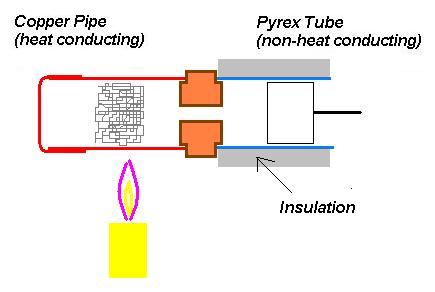
My conclusion then would be that as far as possible, the piston cylinder should be entirely NON-HEAT CONDUCTING. In that way ALL the heat is used to push the piston and none is lost to the cylinder walls robbing power. This contradicts very firmly established "Laws" of thermodynamics, nevertheless, that is what I see.
Image
Tom Booth
Posts: 4670
Joined: Tue Nov 07, 2006 2:03 am
Location: Fort Plain New York USA
Contact:

Re: large lamina flow build

Post by Tom Booth »

In fact, I think I would try this:

Image

The reason I think that the engine with a heat conducting power piston cylinder wont run until it gets hot is that once hot the heat in the gas cannot be dissipated. In effect, the heat, once the cylinder gets hot acts as an insulation in that heat can only flow from hot to cold. If the cylinder were not heat conducting to begin with then it would not be able to rob the air of its heat and so would not have to be hot for the engine to run.

Of course, insulating the heat sink to prevent heat loss contradicts the whole idea of having a heat sink in the first place. Nevertheless, I think it would be worth experimenting with. If the heat is being effectively converted then no heat sink is necessary.
Geoff V
Posts: 121
Joined: Thu Apr 12, 2012 11:49 am

Re: large lamina flow build

Post by Geoff V »

Tom

Where as I agree with much of your argument, I do have trouble with the idea of insulating the cylinder. The article I offered from the University of Gent, suggests that there is a performance advantage if the temperature rise during adiabatic compression can be reduced by a Desaxe offset to the crankshaft, to shorten the duration during which compression takes place and by the unshrouding of the cylinder walls when the piston is in the lower part of the cylinder. This minimises the cooling during the expansion phase yet allows cooling at the start of the compression phase.

During the trials of my vee twin, on which there is Desaxe offset, I noticed a difference in performance depending on the direction of rotation. Running in the direction with the shortest duration for compression produced a slightly lower output, contrary to the Gent analysis, but I now believe this is because I have my cooler as part of the cylinderhead which is cooling the gas during expansion. When I ran the engine in the opposite direction, longest period for cooling, I realised a performace increase because the adiabatic rise during compression had more time to disipate. I feel sure if I removed the cylinderhead cooler the best performance would be realised running in the direct with the shortest duration during compression as per the Gent analysis.

GeoffV
Last edited by Geoff V on Fri Feb 22, 2013 10:32 pm, edited 1 time in total.
derwood
Posts: 114
Joined: Sat Dec 11, 2010 10:15 pm

Re: large lamina flow build

Post by derwood »

same here, I agree with some of Tom's conclusions. Pyrex is the last thing you would want to use for a cooling cylinder, This does raise some questions. Questions that can only be answered with testing. Unfortunately I need a running engine to do the tests. Perhaps the graphite piston aids in cooling. I have seen many versions with brass cylinders that seem to work quite well. The Ted Warbrooke design uses brass and seems to have good power. As far as the copper heat chamber goes, I think copper would be a good choice for the section that comes into contact with the heat source. the rest of the heat chamber would need to be SS. If the heat chamber was all copper it would actually cool the air some before it reaches the cylinder. My tests with mild steel suggest this. One other factor raises questions for me and that is the choke which is commonly costructed from brass. I think that the choke acts as a bit of a delay. The smaller the choke the more delay. As far as the material goes, it seems to always be a good heat conducting material. I would like to find the book for Ted Warbrooke's single piston design because I can't figure out what is going on in that brass section at the base of the piston cylinder.

I once had the idea that inertia played an important role in the function of these engines. Think of a pulse jet engine. After each explosion the pulse jet engine pulls air in for the next explosion. The expanding gasses contract after each explosion and I don't think it is due to any cooling. A good example of this is a jar with some alcohol in it and a small hole in the lid. When you light it you will have a crued pulse jet. The small hole could be the choke. The same thing could be going on inside the lamina flow engine but just not as violently.
Tom Booth
Posts: 4670
Joined: Tue Nov 07, 2006 2:03 am
Location: Fort Plain New York USA
Contact:

Re: large lamina flow build

Post by Tom Booth »

derwood wrote:same here, I agree with some of Tom's conclusions. Pyrex is the last thing you would want to use for a cooling cylinder...
My point or idea as far as using Pyrex or possibly ceramic or something non heat conducting is that I think that this type of engine, (Lamina Flow) works on a different principle than most Stirling engines (that have a displacer).

The energy in a gas expanding is basically Kinetic energy. I think that the "regenerator" or wire mesh serves the purpose of holding heat until the piston returns and at the end of the return stroke gives the gas a kind of jolt which releases the heat. The release of heat is rather sudden and the expanding gas more or less explodes rather suddenly propelling the piston outward. At the end of the pistons outward movement it is moving by its own momentum rather than the continued expansion of the gas. The gas has already given up its energy to the piston in a sudden burst and cooled as a result. The continued expansion of the gas due to momentum of the piston cools it further. At some point the gas gets cold enough that it contracts and the motion of the piston is reversed. It picks up momentum and then at the end of the return stroke it catches up with the contracting gas and begins to compress it or push it at which point the concussion causes another sudden release of heat from the regenerator.
I once had the idea that inertia played an important role in the function of these engines. Think of a pulse jet engine. After each explosion the pulse jet engine pulls air in for the next explosion. The expanding gasses contract after each explosion and I don't think it is due to any cooling. A good example of this is a jar with some alcohol in it and a small hole in the lid. When you light it you will have a crued pulse jet. The small hole could be the choke. The same thing could be going on inside the lamina flow engine but just not as violently.
I'm not too familiar with the pulse jet, but this sounds similar.

Think of a paddle ball.

The heat delivered by the regenerator is like the paddle, the gas is like the elastic rubber band which connects the paddle to the ball and the piston is like the ball.

[youtube]http://www.youtube.com/watch?v=OViXznx9KKo[/youtube]

The point being that in all this there is no reference to cooling via a heat sink. It is a simple transfer of kinetic energy to the piston through the elastic medium - more or less like a paddle ball.

If that is the actual case then heat loss in the power cylinder section when the gas is expanding and pushing the piston would be like holes in a garden hose, neither necessary nor desirable. You can explain everything going on in terms of the heat source (regenerator)/paddle; the elastic (rubber band/gas) and the ball/piston, or as a transfer of kinetic energy. That is; No "heat sink" required.

Of course, that is speculation and could be wrong I suppose, but that's how it looks to me.
derwood
Posts: 114
Joined: Sat Dec 11, 2010 10:15 pm

Re: large lamina flow build

Post by derwood »

Tom, I think you are very close. You are explaining a pulse jet without knowing it. When the gas returns to the heat chamber the piston assists in this return. cooling in the piston cylinder is not what causes the piston to be pulled back in. The air speed is actually increased by the hot expanding gasses in the piston cylinder. The momentum of the increased air speed actually pulls a vacuum on the heat chamber (stretches the air like a rubber band). After the piston reaches the top of it's stroke the gasses are allowed to suddenly return to the heat chamber and the piston is pulled with it. The momentum of the piston and flywheel help to compress the gasses, this compression probably takes place during the last half of the pistons inward stroke. I think some cooling is needed, but only enough so that the gasses rapidly expand again when returned and compressed in the heat chamber. I think cooling should take place after the gasses have expanded in the cylinder. The pyrex allows for a slower/delayed cooling. One thing I forgot to add is that the last half of the piston outward stroke helps to pull a vacuum on the heat chamber. Due to momentum of the flywheel.
Tom Booth
Posts: 4670
Joined: Tue Nov 07, 2006 2:03 am
Location: Fort Plain New York USA
Contact:

Re: large lamina flow build

Post by Tom Booth »

derwood wrote:Tom, I think you are very close. You are explaining a pulse jet without knowing it. When the gas returns to the heat chamber the piston assists in this return. cooling in the piston cylinder is not what causes the piston to be pulled back in...
In regard to the Lamina Flow Stirling. (I still haven't looked into the pulse jet) there is just one qualification I would make:

I think cooling does take place, (in the piston or power section of the engine) even if the cylinder were perfectly non-heat conducting, just not external cooling.

The energy in an expanding gas is kinetic energy. This kinetic energy manifests as what we generally think of as "heat".

So when a gas expands and pushes a piston there is a transfer of kinetic energy. As a result, the gas gives up its internal energy to the piston to drive it and whatever is connected, connecting rod, flywheel, pulley, belt, electric generator or whatever. The energy to move all this mass has to come from somewhere. It is a result of the conversion or transfer of the gas or air's kinetic energy to the piston and all it might be driving.

The loss of the gas's kinetic energy is equivalent to loss of "heat". In this way the gas IS cooled, but the cooling is not due to a transfer of heat to an external heat sink but rather due to a loss or transfer of its internal energy.

In other words, the "heat" is converted into "work".

Originally, this was not recognized in thermodynamics. With all the various terminology there is in that field, I don't think there is even a name for it. (The type of expansion where heat in a gas is converted into work). There is "adiabatic expansion", "isothermal expansion" etc. but if there is a specific term for expansion involving heat being converted into work, I haven't come across it. It is largely treated as though there is no such thing. Not even a word to express the concept. It seems as though it is kind of begrudgingly admitted that such a thing happens but mostly in the context of denial (second law of thermodynamics: "not all of the heat can be converted into work." or "It is not possible to construct an engine which does nothing but convert heat into useful work.") So it is swept under the rug. Mentioned almost exclusively, only in such negative terms.

I'm emphasizing it because I think it is important to keep in mind in designing an engine and I think the Lamina Flow Stirling in particular appears to demonstrate (to me anyway) that it is more than incidental. I think it is what makes it possible for such an engine to run at all, especially if it is of the "free piston" type.

The "heat" (kinetic energy) is ultimately transferred to the load on the engine.

If the load is a generator powering an electric light bulb then the "heat" ultimately "disappears" out of the gas pushing the piston and re-emerges as photons from the light bulb.

If there isn't any load. That is, if the engine isn't doing any "useful work" then the energy meets a dead end and the "heat" has nowhere to go. Then it will have to be dissipated as "waste heat". In fact, a "free piston" type Stirling can't even operate without a load (such as a linear generator). I think this is at least partially true of the Lamina Flow engine. A flywheel is itself a "load" but not a very substantial one.

In other words, for the gas to really cool effectively, It needs to do some useful work. Push against some substantial resistance. Otherwise you end up with a lot of wasted heat that has nowhere to go and then you need a big heat sink to get rid of the excess heat for the engine to be able to run. If the heat is converted into work then the need for a heat sink, if any, is lessened if not entirely eliminated.

I suppose some waste heat is inevitable, that doesn't mean it shouldn't be minimized.
derwood
Posts: 114
Joined: Sat Dec 11, 2010 10:15 pm

Re: large lamina flow build

Post by derwood »

Yes, I agree with you. some cooling is taking place in the piston cylinder. When the gasses expand they are cooled, no doubt about that. I am just saying that if you look at this engine from an inertia point of view that the cooled gas does not contribute much to pulling the piston back in. Enertia at the heat source is resposible for this. I don't know if I am correct but inertia does seem like a logical explaination for the laminar flow engine. Also, if this is correct, the shape of the nozzle (concave at the piston side and more tapered on the heat side) is very important for power increase. Turbulance will decrease power. It is obvious that the stirling cycle does not apply to this and the fact that I have been using this as a basis for design has made it an obvious failure.
Last edited by derwood on Wed Jan 23, 2013 2:58 pm, edited 2 times in total.
Tom Booth
Posts: 4670
Joined: Tue Nov 07, 2006 2:03 am
Location: Fort Plain New York USA
Contact:

Re: large lamina flow build

Post by Tom Booth »

derwood wrote:Yes, I agree with you. some cooling is taking place in the piston cylinder. When the gasses expand they are cooled, no doubt about that. I am just saying that if you look at this engine from an enertia point of view that the cooled gas does not contribute much to pulling the piston back in. Enertia at the heat source is resposible for this. I don't know if I am correct but enertia does seem like a logical explaination for the laminar flow engine. Also, if this is correct, the shape of the nozzle (concave at the piston side and more tapered on the heat side) is very important for power increase. Turbulance will decrease power. It is obvious that the stirling cycle does not apply to this and the fact that I have been using this as a basis for design has made it an obvious failure.
Well, I can't really say I follow your reasoning or understand what you mean by inertia in this context.

I've looked into the pulse jet a little, in that context I can understand. It seems not unlike how a two cycle IC engine works, that is, the exhaust on its way out pulls the intake air/fuel mixture into the cylinder. Once the flow is started in that direction it tends to continue. A Stirling though, is external combustion so has no actual exhaust or intake, so I don't really see how this inertial flow could have a bearing.

Of course, I haven't attempted to build a Lamina Flow Stirling large or small so I'm just talking out my hat. I have my own ideas on how this engine works. Like I don't agree that turbulence is necessarily a bad thing, especially once the air stream hits the regenerator or heat exchanger. In fact, I don't see how it could be avoided in any case. I think turbulence is necessary for good heat exchange.

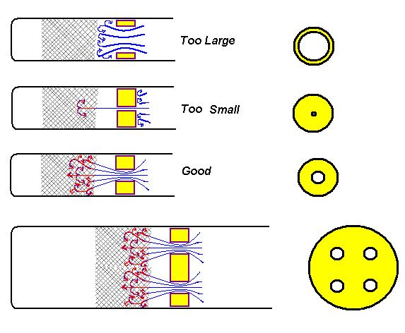
Anyway, on that note, I have been mulling over the size of the "choke" or orifice issue for a while and had an idea you might want to try.

I read somewhere a while back, don't remember where exactly, but it had something to do with Stirling Engines and a study on the orifice size. (Not necessarily Lamina Flow, I think it had to do with an LTD type engine with holes in the displacer)

Anyway, it said that a hole of 1/8 inch diameter, If I remember correctly, made the best stream of air for impacting the heat exchange area so as to maximize heat uptake to heat and expand the air stream. Smaller and the air flow was too restricted. Larger and the air stream was too diffuse.

If this applies to the Lamina Flow, which I think it should, then the problem is, with a small engine, like with a 3/4 in test tube, a 1/8 inch hole would probably work fine but when you go to a bigger size there is a problem in that for more power for the bigger engine you need more air flow, but if you increase the size of the orifice you loose the narrow jet of air which is what can penetrate the regenerator effectively for maximum heat exchange.

So what I think I would try is maybe keep the 1/8 in hole but just use more of them as required according to the size of the engine. Needless to say this doesn't do anything to minimize turbulence but I think it might be worth a try.

I drew up a little sketch to better illustrate what I mean:

Image
derwood
Posts: 114
Joined: Sat Dec 11, 2010 10:15 pm

Re: large lamina flow build

Post by derwood »

I recently purchased some 4in. graphite bar stock for piston material. I was surprised how easy it was to machine. The graphite piston made a huge difference. My first test showed more signs of running. When I removed the piston rod, I was surprised to see thar it ran very well in free piston mode. I even clamped a pair of vise grips to the piston for added weight and it still ran, just a little slower. It ran at about 1200 stokes per minute which would be 600 rpm if using a crank shaft. I still could not get it to run with a crank shaft and fly wheel. I tried different strokes, fly wheel weights and compression ratios but the piston travel was always to short to make a full revolution. It would rock back and forth for a while but would not run. When I reduced the choke diameter it made a big difference. It no longer would run free piston mode but it now runs with crank shaft and fly wheel. Choke size seems to have a direct effect on stoke length. I think it determines the delay. The smaller the choke the more delay you get. Also cooling the cylinder does seem to increase power but cooling the choke seems to decrease power. I believe a heat break is needed where the choke meets the cylinder. It has a 3.625 in. bore and a 2.5 in stroke. it is currently running at about 110 rpm but seems to have good torque. I think the compression is to high and will probably run faster once this is adjusted.
Geoff V
Posts: 121
Joined: Thu Apr 12, 2012 11:49 am

Re: large lamina flow build

Post by Geoff V »

Derwood

Thanks for your progress report.
derwood wrote:Also cooling the cylinder does seem to increase power but cooling the choke seems to decrease power
I note with interest that your findings regarding cooling reflect my experiences and are very much inline with the article from the Univeristy of Gent.

Keep up the good work.

GeoffV
derwood
Posts: 114
Joined: Sat Dec 11, 2010 10:15 pm

Re: large lamina flow build

Post by derwood »

Thought i would post a video of what I have so far. It's a short vid because I could not find my memory card to the camera. I think maybe the stroke is to long. Think I will try a shorter stroke with the same compression ratio. The piston is 3.36 in. and the stroke is 3 in. I also think it has some heat exchange issues on the hot side. The stainless i'm using is kind of thick, .075 in. It also seems to have good torque. I think it is capable of much higher speeds but it is all trial and error. slow progress!


http://s380.beta.photobucket.com/user/d ... 2.mp4.html
Geoff V
Posts: 121
Joined: Thu Apr 12, 2012 11:49 am

Re: large lamina flow build

Post by Geoff V »

Derwood

Thanks for the video, if a picture is worth a thousand words then a video is worth several thousand.

I spent much of the week trying to analyse the effect of the choke on the TL cycle and thought my preliminary results may help you decide on your next move. The main problem encountered was controlling the temperature of the heater as any small change has a big impact on the power output, however with this in mind I hope the following is of interest.
I started by fitting a weeny Prony brake and plotted the torque from 1000rpm to 2000rpm to establish a 'base line'. The curve is fairly flat, as one would expect, delivering peak power at 1400 rpm (off load speed 2400rpm) of 1.57w from 20cc or 0.0785w/cc. The cooler/cylinder head was then removed and the inner pulse tube supported by three wire legs so there was no restriction between the cylinder and the pulse tube. The engine self started! and ran very smoothly but at reduced power and with a lower 'off load' speed.
IMAG0445.jpg
IMAG0445.jpg (113.2 KiB) Viewed 13535 times
IMAG0449.jpg
IMAG0449.jpg (92.55 KiB) Viewed 13535 times
Next a plastic choke of 10mm bore was fitted ( to minimise conduction and therefore rely only on the cylinder walls for cooling). The engine ran well with an off load speed of 2200rpm but at a slightly lower power output than with the original cylinder head cooler and with a noticable rise in cylinder wall temperature. Next the choke bore was increased to 11.8mm bore, this increased the performance to a level very similar to the 'base line' but the off load speed rose to 2600rpm, best so far.
Clearly the choke is not necessary for the engine to run, however by adding a restriction between the cylinder and the pulse tube it appears that there is a rise in adiabatic heating in the cylinder some of which is removed through the cylinder walls before the air enters the pulse tube. There must also be a slight delay but as the delay occurs during both compression and expansion I doubt that it contributes to the power output.

Observations so far with this engine.
The reverse flow pulse tube shortens the overall length of the engine considerably and with its slotted heat exchanger, heat transfer is very good.
Cooling by the cylider walls alone improves performance.
The choke restriction probably enhances the cooling phase, will reduce free speed if too small, yet is not necessary for the engine to run.

Next move for me is a finned, hard anodised cylinder to improve (hopefully) the cooling.

GeoffV
Tom Booth
Posts: 4670
Joined: Tue Nov 07, 2006 2:03 am
Location: Fort Plain New York USA
Contact:

Re: large lamina flow build

Post by Tom Booth »

derwood wrote:Thought i would post a video of what I have so far. It's a short vid because I could not find my memory card to the camera. I think maybe the stroke is to long. Think I will try a shorter stroke with the same compression ratio. The piston is 3.36 in. and the stroke is 3 in. I also think it has some heat exchange issues on the hot side. The stainless i'm using is kind of thick, .075 in. It also seems to have good torque. I think it is capable of much higher speeds but it is all trial and error. slow progress!


http://s380.beta.photobucket.com/user/d ... 2.mp4.html
Wow! congratulations on getting it running!

Out of curiosity, are you using any kind of regenerator ?
Ian S C
Posts: 2218
Joined: Thu Dec 02, 2010 5:15 am
Location: New Zealand

Re: large lamina flow build

Post by Ian S C »

derwood, had a look at your vidio, I wounder if a better weight distribution on your flywheels might help for a starter. It could be done by drilling a hole near the end of each arm, and put a bolt in, and add extra weight, this would be the equivalent of having a rim on the wheels, its out there where the weight is required. The bearings, have you removed the grease, and used light grade oil. I think you need to try a crank with adjustable throw, but you have to have some way of testing the power output, because as you reduce the stroke the speed should go up, but the torque may come down, you want the highest of both. Reduce the stroke by small amounts each time, you may find that the power output is fairly flat over quite a wide range. The vidio was quite good, but I could not get more than 4sec on my dialup, so I had to wait until I could get on Broadband. Ian S C
Post Reply