Tesla's "Ambient Heat Engine" Experiment

Discussion on Stirling or "hot air" engines (all types)
Tom Booth
Posts: 4714
Joined: Tue Nov 07, 2006 2:03 am
Location: Fort Plain New York USA
Contact:

Re: Tesla's "Ambient Heat Engine" Experiment

Post by Tom Booth »

Jack wrote: Thu Dec 07, 2023 10:29 pm I like your theories!
I do agree with the cooling by expansion part. It would take a lot of testing to get it right though. Especially for it to be a closed cycle. Because if it doesn't cool down enough you end up with continually hotter and hotter cycles. And there isn't very much separation of zones in a rotor, the cold side will heat up pretty fast as well, just from conduction.
Well...

I suppose that could be a problem, but there are materials with very low heat conductivity. Also,

Well, take this experiment I did recently:

https://youtu.be/LG09AXAjpio?si=l2rEo6Pib-XARWlA

Exactly why, I'm not entirely certain, but I'm heating the hot side of the engine almost continuously with a propane torch. That's about 3,500° F.

Styrofoam has a melting temperature of less than 500° F

I don't think the expansion side (power cylinder) ever got anywhere near hot enough to melt the Styrofoam, but at any rate, however hot it may have gotten, INSULATED, with no external cooling, the engine kept on running. The heat never built up enough to melt the Styrofoam, if it ever built up at all, which it seems never happened.

After making that video, I removed the Styrofoam and the power cylinder still felt cool to the touch.

So... To me that looks like by expansion cooling alone (including conversion of heat to "work"), that is, with no external cooling, the engine was able to maintain a temperature difference of at least a few thousand degrees, seemingly indefinitely.

My personal opinion, based on a lot of observations and experiments, is that these engines act like heat pumps or a vapor/compression/expansion refrigeration system.

While expanding into the power cylinder, the working fluid is becoming cold enough to absorb heat away from the cylinder walls in the same way the expanding gas (refrigerant) passing through an expansion valve draws heat away from the walls of the evaporator tubing.

144037528_s.jpg
144037528_s.jpg (67.54 KiB) Viewed 16059 times

So if some heat is conducted, if cooling is actually taking place, the little bit of heat that might be conducted across a mostly non-conductive medium might be inconsequential.
...
I would love to find a way to run one rotor inside another. As that would solve a few issues for my plan. So if you have any thoughts on that I'd be happy to hear/read them.
Not sure what you mean or what the purpose of that would be.
Jack
Posts: 221
Joined: Wed Nov 01, 2023 2:01 am

Re: Tesla's "Ambient Heat Engine" Experiment

Post by Jack »

Well if you're thinking of turning that drawing into a rotary design you'll have to run a rotor inside a rotor.
Tom Booth
Posts: 4714
Joined: Tue Nov 07, 2006 2:03 am
Location: Fort Plain New York USA
Contact:

Re: Tesla's "Ambient Heat Engine" Experiment

Post by Tom Booth »

Jack wrote: Fri Dec 08, 2023 4:04 am Well if you're thinking of turning that drawing into a rotary design you'll have to run a rotor inside a rotor.
Well,...

That might be possible.

There was a patent or patent application for a two stage duel rotary vane compressor
Patent-of-a-two-stage-dual-vane-compressor-3.png
Patent-of-a-two-stage-dual-vane-compressor-3.png (101.79 KiB) Viewed 16027 times
But what I had in mind was not that, but similar in that the vanes would be "shared" and the vanes would travel in a grove, but what I drew would look like a break rotor with the vane guide a disk in the center of a stationary rotor, rather than a circle, and with the vanes sliding from side to side rather than in and out from center.

Similar to a cylindrical or barrel cam:
zylindernutkurve1.gif
zylindernutkurve1.gif (544.24 KiB) Viewed 16027 times
Imagine my drawing wrapped around a cylinder similar to the above gif but the vanes traveling in the grove and cylinder stationary.

duel-vane-engine.jpg
duel-vane-engine.jpg (558.43 KiB) Viewed 16020 times
VincentG
Posts: 1056
Joined: Tue Feb 21, 2023 3:05 pm

Re: Tesla's "Ambient Heat Engine" Experiment

Post by VincentG »

Tom could you perform the same test with the engine not running and observe the temperature of the expansion side? Seems like a really simple way to get conclusive results.
Tom Booth
Posts: 4714
Joined: Tue Nov 07, 2006 2:03 am
Location: Fort Plain New York USA
Contact:

Re: Tesla's "Ambient Heat Engine" Experiment

Post by Tom Booth »

VincentG wrote: Fri Dec 08, 2023 7:22 am Tom could you perform the same test with the engine not running and observe the temperature of the expansion side? Seems like a really simple way to get conclusive results.
Conclusive of what?

I mean, if the piston isn't moving, no heated air is going much of anywhere, to heat anything or otherwise.

Anyway, why not? It could be done, just kind of seems like apples to oranges, though I did some similar experiments with LTD engines running and not running on ice (ambient heat), which ended up getting me banned from the physics forum.

Logically, I would think what I say here would also be true of an LTD. That is, if you have an LTD engine just sitting on a cup of ice, the ambient heat from above should reach the ice more slowly. The displacer is an insulator and just sitting there covering the ice keeping it cold. Not running, the engine is just a lid on an ice chest keeping the outside hot air away, so the ice should melt more slowly.

With the engine running, on the other hand, the warm ambient air in the top is constantly being exchanged with the cool air below the displacer. That would be like lifting the lid on an ice chest up and down fanning the ice with the warm ambient air. So, the ice should melt faster when used to run the engine.

However, IF the engine is actually actively converting the ambient heat into mechanical work and/or acting as a heat pump expanding the air and taking heat away from the cold side, or somehow preventing the heat from ever reaching the cold side (in spite of the active and continuous fanning or circulation of the air by the displacer), well, maybe, just maybe, the ice used to run an LTD engine would stay cold longer, but I would think, for that to happen, the engine would have to be causing some cooling by some means or other.

Spoiler alert!

https://www.physicsforums.com/threads/s ... ne.991714/

In this case though, with a high temperature thermal lag (or whatever) type engine, there is no displacer to either insulate or "fan" with hot air, the power cylinder area.

What theory would we be testing?

I think it would be worth doing, and could be interesting, but I don't think the results would be as clear cut as with the LTD running or not running on ice.

If the power piston chamber heats up in the not-running engine, is that due to conduction or convection? Would any hot air move into the power cylinder at all?

Of course, if the power cylinder actually cooled down to some sub-ambient temperature, (with the engine running) that would be pretty extraordinary.
VincentG
Posts: 1056
Joined: Tue Feb 21, 2023 3:05 pm

Re: Tesla's "Ambient Heat Engine" Experiment

Post by VincentG »

Conduction of heat alone in a stationary engine would eventually heat up the expansion side to "X" temperature, while running the engine would eventually reach "Y" temperature.

While I do think the running of the engine can provide cooling, that would be an important variable in the test.
Jack
Posts: 221
Joined: Wed Nov 01, 2023 2:01 am

Re: Tesla's "Ambient Heat Engine" Experiment

Post by Jack »

Tom Booth wrote: Fri Dec 08, 2023 6:01 am
Jack wrote: Fri Dec 08, 2023 4:04 am Well if you're thinking of turning that drawing into a rotary design you'll have to run a rotor inside a rotor.
Well,...

That might be possible.

There was a patent or patent application for a two stage duel rotary vane compressor

Patent-of-a-two-stage-dual-vane-compressor-3.png

But what I had in mind was not that, but similar in that the vanes would be "shared" and the vanes would travel in a grove, but what I drew would look like a break rotor with the vane guide a disk in the center of a stationary rotor, rather than a circle, and with the vanes sliding from side to side rather than in and out from center.

Similar to a cylindrical or barrel cam:

zylindernutkurve1.gif

Imagine my drawing wrapped around a cylinder similar to the above gif but the vanes traveling in the grove and cylinder stationary.


duel-vane-engine.jpg
That patent is a nice idea, but mechanically very difficult to do. Volumes of the chambers would be different to each other, vanes wear and don't seal anymore, not to mention trying to just get it to work with bearing placement. I'm struggling with this exact problem at the moment.

The barrel idea has similar mechanical issues. Sealing being the most difficult one as you just introduced more sealing surfaces. And probably the barrel will still have to be the turning part, to get the work onto an axle to be useable.
But it might be that I'm just missing something.
I saw you mention in another thread somewhere how scientist are blind to new ways. It's a human problem in general, one that I suffer from as well. Once you turn in one direction it's very difficult to see the other direction.
Tom Booth
Posts: 4714
Joined: Tue Nov 07, 2006 2:03 am
Location: Fort Plain New York USA
Contact:

Re: Tesla's "Ambient Heat Engine" Experiment

Post by Tom Booth »

Jack wrote: Fri Dec 08, 2023 6:10 pm ...
The barrel idea has similar mechanical issues. Sealing being the most difficult ...
Yes, I get the impression that is a problem with rotary vane devices generally. I have some virtually new, hardly ever used air tools that I found were rotary vane, and basically the air goes straight through until they get up to speed and the centrifugal force starts to create a positive seal.

My side winder rotor would not be able to take advantage of centrifugal force so the sidewall tolerances would have to be, quite likely, impossibly close and non-contact, no friction, like a NASA Stirling. But those things run for decades with no wear but that's probably not possible to achieve with a rotary vane design.

Still, my 2001 Ford Ranger pickup truck IC engine likely has many more high friction, high wear parts but still runs great after more than 20 years.
Jack
Posts: 221
Joined: Wed Nov 01, 2023 2:01 am

Re: Tesla's "Ambient Heat Engine" Experiment

Post by Jack »

Another thing I later realised is that the barrel idea creates force in the length of the axle, which has to be translated to across the axle. That always creates more friction and loss.

I found the whole patent you were talking about and it seems they talk about a second version that's very promising. I'm exploring that further.

Image
Tom Booth
Posts: 4714
Joined: Tue Nov 07, 2006 2:03 am
Location: Fort Plain New York USA
Contact:

Re: Tesla's "Ambient Heat Engine" Experiment

Post by Tom Booth »

The design I drew was literally off the top of my head so who knows if it's even possible. According to classical thermodynamics, no.

Well, actually I'm not sure about that. From what I understand the Carnot limit is supposed to apply to reciprocating engines where the piston needs to reverse course and return to TDC.

Now I'm wondering if there could be ports open to atmosphere, making it functionally an "atmospheric engine" similar to a flame licker, but with ports rather than a valve.

Another thought regarding friction. The ferrofluid seal came to mind.

The idea of a Ferrofluid piston seal was floated in here a while back

viewtopic.php?f=1&t=5477&p=18034

and I had plans to experiment with that, but the bottle of Ferrofluid is still sitting on the shelf in my shop so far, But I noticed now that Ferrofluid "o-rings" are actually being used industrially already and there are companies currently fashioning "custom" Ferrofluid seals for various applications. I couldn't locate anything involving Ferrofluid in a rotary vane type application, but for a closed cycle, hermetically sealed engine, that seems quite feasible, the stuff cannot go anywhere.

Magnetized vanes "lubricated" with Ferrofluid, or vanes with a magnetic strip along the edges.

Ferrofluid used in Stirling engines, a few videos:

https://youtu.be/21WzdjqAG0s?si=3Ymw8goaJHKeKsj4

https://youtu.be/3Uh0pBJ5QW0?si=8AdXY17cOlPDhF2n
Tom Booth
Posts: 4714
Joined: Tue Nov 07, 2006 2:03 am
Location: Fort Plain New York USA
Contact:

Re: Tesla's "Ambient Heat Engine" Experiment

Post by Tom Booth »

That gives me another idea.

I've been struggling for, seems like years, to come up with a good design for an "adjustable" air spring.

What kind of tensioner to use? How to make it work over various levels of pressurization? How to keep the air-spring piston positioned and centered?

Magnets and Ferrofluid!

Something like this:

Resize_20231209_133833_3821.jpg
Resize_20231209_133833_3821.jpg (160.56 KiB) Viewed 15332 times

The hair thin passage through the center of the piston is for pressure equalization.

The half round objects are the magnets embedded in the piston and cylinder walls that hold the ferrofluid in place creating a perfect frictionless seal and also keep the piston properly positioned regardless of the level of pressurization.
matt brown
Posts: 751
Joined: Thu Feb 10, 2022 11:25 pm

Re: Tesla's "Ambient Heat Engine" Experiment

Post by matt brown »

Tom Booth wrote: Wed Apr 11, 2012 8:52 am According to an article by Nikola Tesla some of the HEAT passing through a heat engine is CONVERTED into some other form of energy (mechanical motion, momentum etc.) and so never reaches the "sink". He envisioned that given a heat engine running on Ambient heat with great enough efficiency - so little of the heat would reach the sink (ice as a heat sink for example) that the power produced by the engine could be used to remove what little heat actually reached the sink allowing the engine to operate indefinitely.
Tom - care to revisit your past ? Before you open your mouth anymore on Tesla's ambient engine, I'd suggest you read ALL YOUR PAST POSTS on such.

list - this thread is 12 years old and loaded with many of Tom's wild speculations which later became his soapbox reality. Oddly, I even bumped into Tom's Tesla-test graphic, again.
Tom Booth wrote: Wed Apr 11, 2012 8:52 am My question is, does the Ambient heat running a heat engine actually get converted as Tesla imagined or is the heat just intercepted in its passage but continues on its way like the water over a water wheel?

I thought up an experiment which could demonstrate the theory one way of the other.

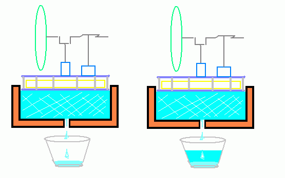
Take two identical LTD type Stirling Engines and set them on top of two identical insulated Styrofoam or perhaps wooden pans full of equal amounts of ice. (Something non-heat conducting at any rate) so that the Ambient heat can only reach the ice by passing through the engines (predominantly anyway). Have a small hole in the bottom of each pan with a water glass underneath.

Now set the engine on the left running but leave the other engine idle or disabled.

Image

Tom Booth wrote: Wed Apr 11, 2012 8:52 am If Tesla was right, the ice in the pan on the left with the running engine on top should melt more SLOWLY than the pan on the right with a non-operational engine since the running engine is converting some portion of the heat trying to reach the ice into another form of energy.

WTF ??? The heat flow is from ambient to ice, so the ice will melt faster (on left) depending upon engine efficiency as Ian later comments. The engine "running on ice" is an observation that can lead to bogus conclusions. The only way that the ice will melt slower (on left) is via reversing the cycle with a motor producing reefer effect.

A proper test would have both engines running (passing equal amounts of ambient air) while only left engine has load. However, at this scale, all values are so small that I doubt any test would be conclusive.

Geez, this ain't rocket science...
Tom Booth
Posts: 4714
Joined: Tue Nov 07, 2006 2:03 am
Location: Fort Plain New York USA
Contact:

Re: Tesla's "Ambient Heat Engine" Experiment

Post by Tom Booth »

matt brown wrote: Sun May 19, 2024 12:35 am ...
Tom Booth wrote: Wed Apr 11, 2012 8:52 am ..If Tesla was right, the ice in the pan on the left with the running engine on top should melt more SLOWLY than the pan on the right with a non-operational engine since the running engine is converting some portion of the heat trying to reach the ice into another form of energy.
...
The only way that the ice will melt slower (on left) is via reversing the cycle with a motor producing reefer effect.

...
(Emphasis added.)

How do you account for the actual test results then?

Again, are you the same "Matt Brown".?

Supposedly you've been reading my posts on this subject since Yahoo groups was a thing. How many many years ago? (2008-2009 ?)

viewtopic.php?p=17048#p17048

You (or some "Matt Brown") has been in here for the past two years doing hardly anything else but bashing my theories and experiments.

Now you act like you're seeing all this for the first time???

Weird.
Tom Booth
Posts: 4714
Joined: Tue Nov 07, 2006 2:03 am
Location: Fort Plain New York USA
Contact:

Re: Tesla's "Ambient Heat Engine" Experiment

Post by Tom Booth »

An Air-cycle refrigeration system works by:

1) compressing air
2) releasing the compressed air through a turbine or reciprocating piston engine to extract work from the air.

A Stirling engine appears to do the same thing, or carry out the same process.

Air is compressed in the cylinder. The air then expands doing work.

Process and result in both instances is the same. Extracting work from the expanding gas results in heat being converted to work, which produces a refrigerating effect.

The difference is that an air cycle refrigerator is optimized to produce a cooling effect while the Stirling engine is optimized for work output.
Fool
Posts: 1242
Joined: Sun Jul 16, 2023 9:14 am

Re: Tesla's "Ambient Heat Engine" Experiment

Post by Fool »

Tom Booth wrote: Sat Jun 20, 2020 8:04 pm Another thing I think happens is on the return stroke the air in the cylinder is compressed, maybe not to the extent that air is compressed in a fire piston, but the principle is the same.

https://youtu.be/-39wmSBO2FM
It seems strange that you have ignored that fact and are now attempting to conjure up a non observed "contraction" to deny it.

The work gained in expansion is lost in isentropic compression.

Cooling it during compression saves energy. That is why it colloquially is called converted. And it is internal energy that is rejected as heat. And it is internal energy that is "converted to work", not heat.
Post Reply